|
|
|
|
|
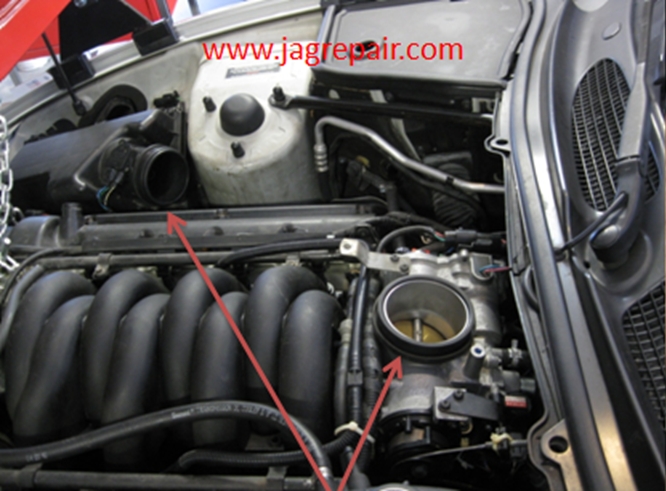
Replacement of the Left HandEngine MountI had a leaking engine mount on the left had side and decided to replace it. I was testing the MAFS when I watched the engine rise up a few inches in the test and felt it was time to replace it. The process is not difficult if you have a lift and you do not break a bolt. First you need to suspend the engine from the top to enable access to the engine mount and enable you to remove it. The other is for you to drop the rack for the steering and that is not difficult if you do not break a bolt like I did. The removal of the shock mount is not hard once you get the top nut off the engine mount and I found this could be done from the bottom with a breaker bar and a short-well socket, the bottom bolt has easy access. This process can be done on the ground with the car on stands and a jack with blocks to push the engine up from the bottom. When I started to think about doing this I had two ways of doing it the first was this way dropping the steering rack and replace the one engine mount or drop the sub frame and replace both engine mounts I elected to do the one mount replacement.
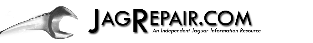
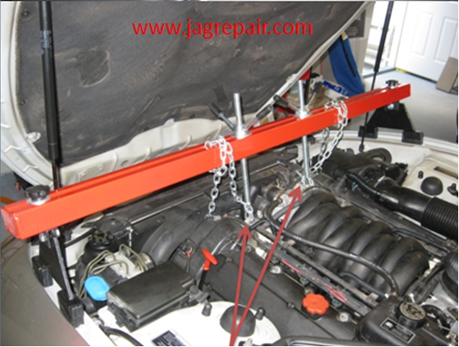
This is the engine support beam to lift the engine weight from the engine mount.
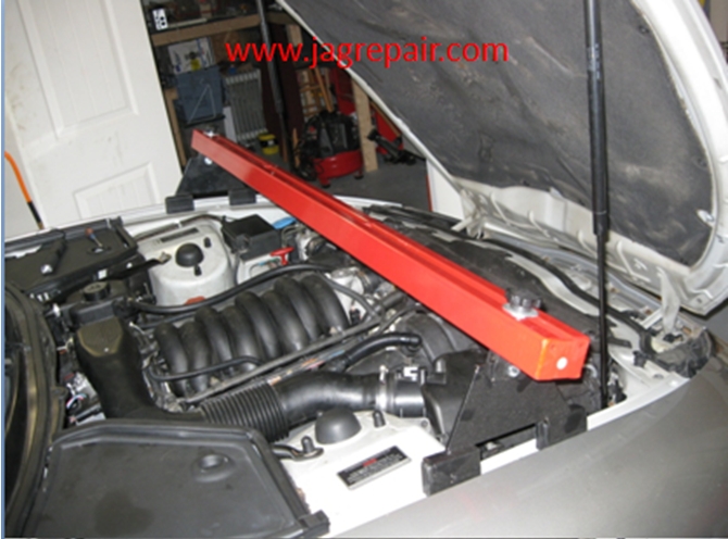
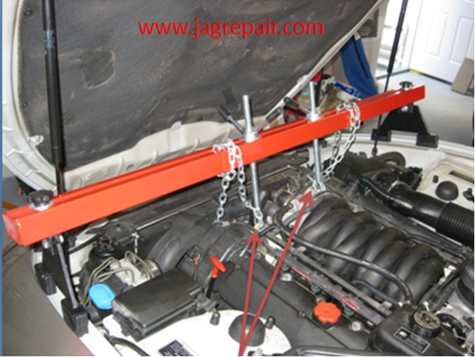
The engine has 2 lifting loops so all I needed to do was to slip the chain through and fasten it to the lifting brackets.
Removed the TB intake pipe.
Once I removed the TB intake pipe I lifted the engine using the wing-nuts. What I did was tighten the one to the right just a little and tightened the one to the left to lift the engine. As you are doing this you need to pay attention to the hood lifts so you do not apply pressure to bend them and you also do not want to crush anything on the back end of the engine. I can tell you I turned the wing-nuts on the left about three different times to get the proper clearance I needed under the car so use caution and if it is not high enough lift it a little higher.
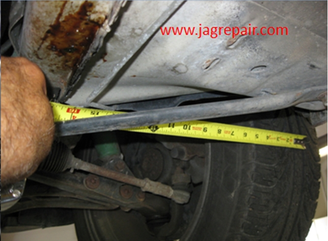
Under the car you will need to drop the steering rack. Before I did that I took several readings and made markings so I could get it back the way it was. I need to be straight with you, I still did not get it right but that is my problem.
marked the steering knuckle and took the bolt loose. Still did not help me!
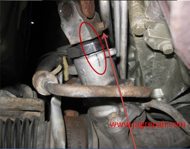
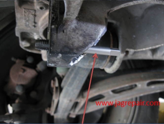
You have 4 bolts to remove, two for each bracket on the steering rack. I treated all 4 with PB Blaster the night before in hopes of making the project easier.
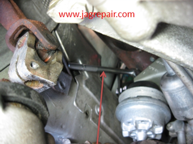
As you can see, one of the bolts did not see it my way. It was the day from hell!
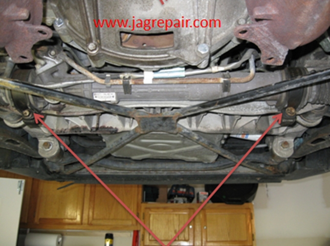
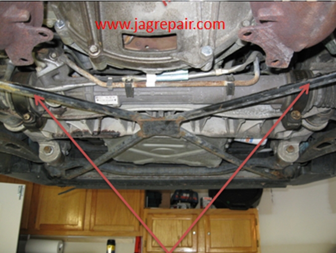
When the steering rack was dropped I could see that space was minimal and so I unbolted the cross beams for better access. I should mention that you need to use caution not to bend, pull and/or tug on the rack because of the hoses and pipes and the related connections.
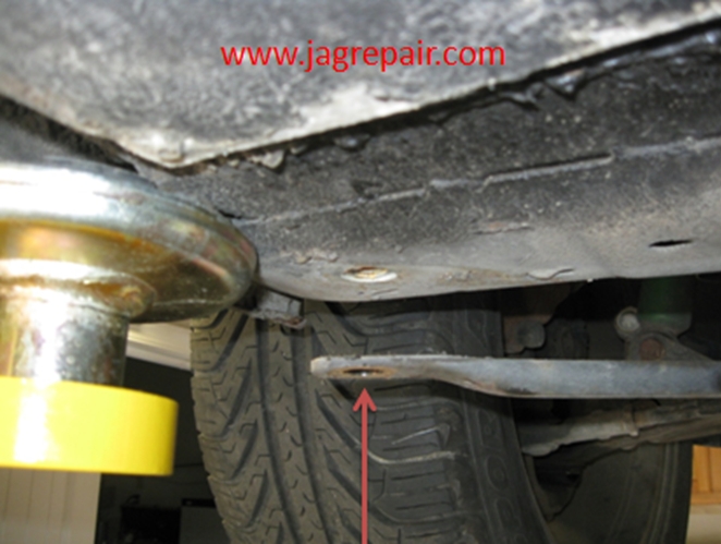
Left cross beam bolt.
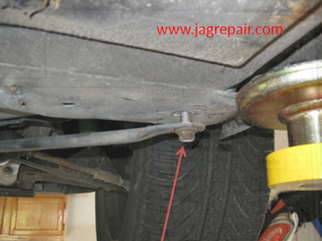
Right cross beam bolt.
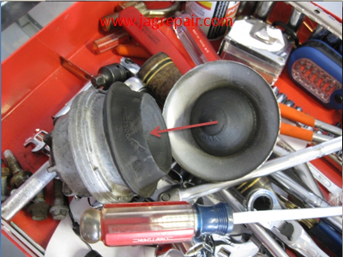
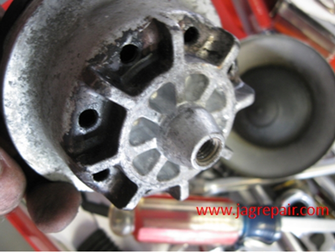
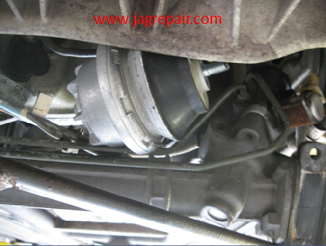
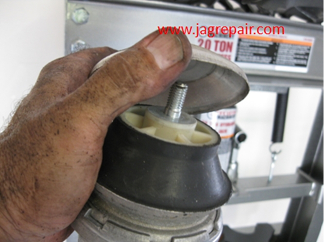
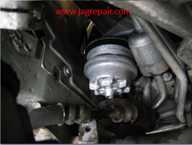
This is the old engine mount. It is not a 2 part item.
This is the underside of the shock mount. Notice the black that is the fluid that has been seeping out. Yes, I know I did not take photos of the removal. I was so happy to get it out I forgot….. I will show how to install and the removal is the reversal.
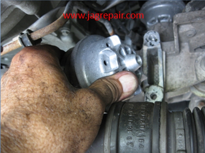
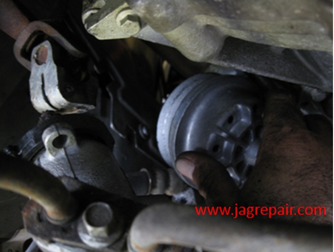
With the steering rack down I slid the mount from the right of the steering rack and slid it to the left.
Sliding it to the left along the steering rack.
All the way to the left and now to put it into position.
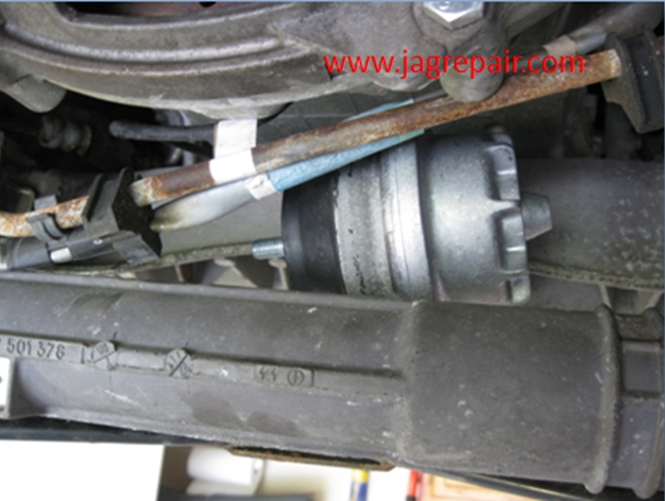
The engine mount is in position and I started bolting it on when I realized that I was missing the hood so, I had to unbolt it and install the hood. Note in this photo, I used a breaker bar and a short-well socket from the bottom to tighten the top nut. Access was much better from the bottom than the top.
The placement of the hood.
The hood is in place!!! I did not take a photo of installing the bottom bolt but I am sure you can figure that one out on your own.
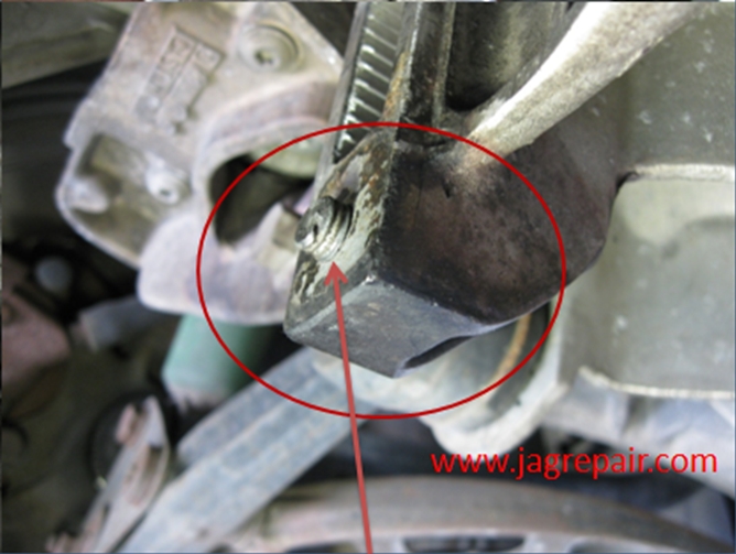
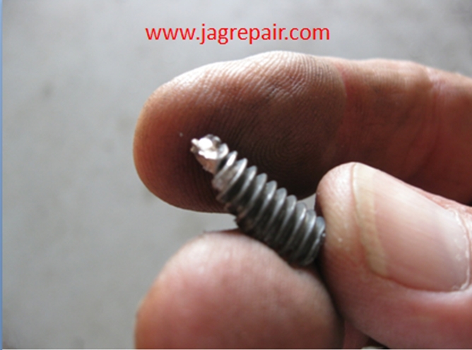
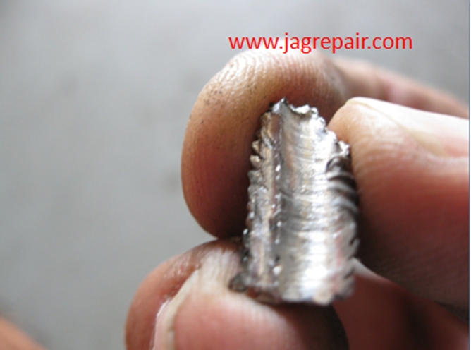
Now to take on the broken bolt. Joy!
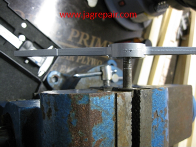
Took out the tap and die set and began working. I used the die to check the threads on the bolts.
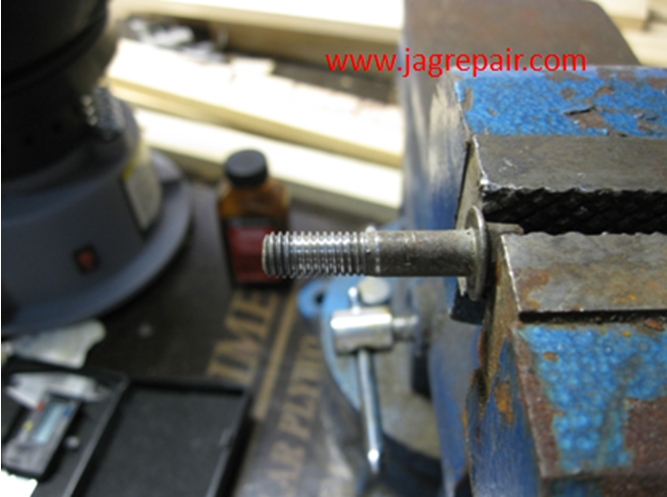
The finished product.
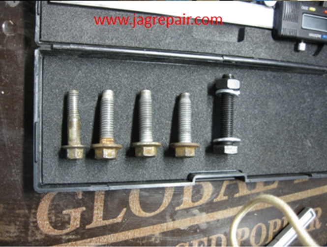
The new bolt was the same rating as the existing bolts.
After drilling and chipping the old bolt out I re-taped the hole and all was good. Installed the bolts and torqued as required.
|
|
|