|
|
|
|
|
Alignment and Ride
Improvements
For several months I have ignored the thunking from under my car each and every time I would go over a road imperfection. Also a few months ago I had to get the right side lower ball joint and tie rod end when I noticed the tire wear, $800.00. Today I elected to do my own repairs so under the car I went and found several things to repair. 1 - Left and right upper rear control arms 2 – Right tie rod end 3 – Front and rear stabilizer links 4 – Left and right rear outer tie rods 5 – All 4 lower shock bushings 6 - Stabilizer Bar Bushings
It took me 2 days. The first day was to replace everything but the shock bushings and I did them on the second day. I should also mention that I did not take all the photos I should have but the job was not difficult to do.
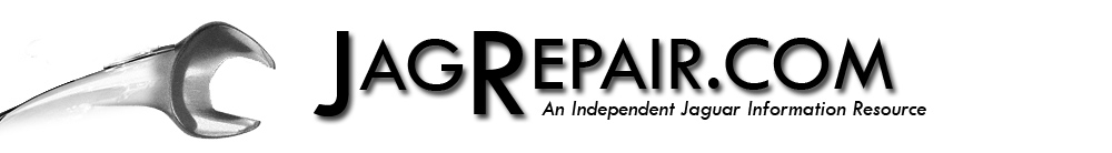
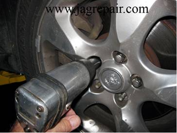
Like any other suspension work, get the wheels out of the way. I did spray all the bolts and nuts associated with the removal and install of each part with PB Blaster in the anticipation of a rusted or corroded item. Front
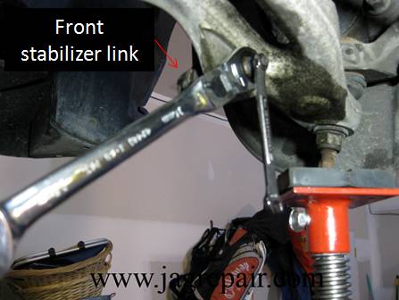
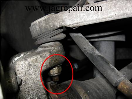
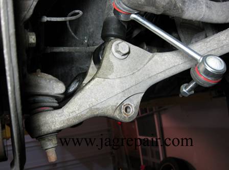
Stabilizer links Left & Right.
The stabilizer links were not as difficult to replace as I thought. You can see the stand under the hub but that was not necessary. The most difficult part was to hold the link shaft in place at the same time I removed the nut. It is suggested that you do that to prevent damage to the control arm.
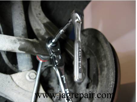
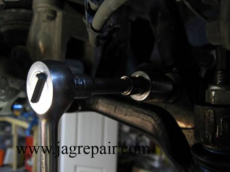
Photo of the new one being installed. Right Tie
Rod End The right tie rod end had a little slop that caused an alignment problem. The left side had already been replaced.
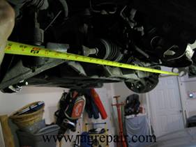
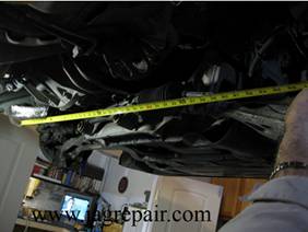
Prior to removing the tie rod end I wanted to take measurements for both sides. Both measurements were taken from the tie down loops for a fixed location. I took the loop on the right to measure the left and used the one on the left to measure right. Doing this helped me in the event I were to change the disposition of the steering that would prevent me from installing the new one as close to correct as possible.
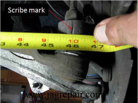
I marked both left and right hubs and documented the measurements for both sides to have the alignment as true as I can until I can get it aligned. I then removed the nut and pulled it down from the hub.
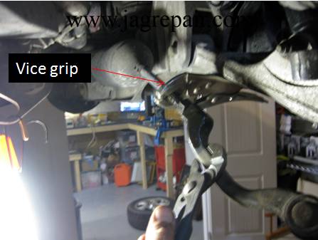
I took my vice grip and clamped it down on the shaft to the tie rod end and used the bottom of the lower control arm to limit movement and help in the removal. I loosened the locknut and removed the control arm.
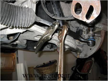
Installed the new control arm and used my measurements to true it as best I could. It was a good thing I took measurements on both sides because I did manage to move it about 3in and had to put it back. Yes that is a crescent wrench! My metric set was one short of fitting. Rear Outer
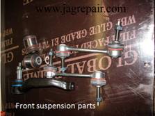
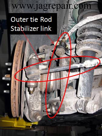
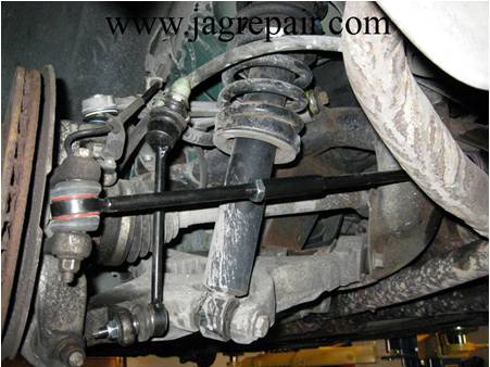
Tie Rod & Stabilizer Links
Before
After
The R&R of the outer tie rod and stabilizer links were straight forward. However, I did the same type of measurement for the rear as I did for the front to keep it in line. Rear Upper
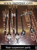
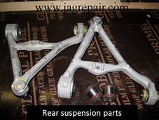
Control Arm
I was a bit concerned about removing the old control arm and the reason was that Jaguar recommends that you remove the axel, brake caliper, ABS outer tie rod and the hub, then take the upper control arm off. Also, how was I going to use a ball joint separator to get that ball joint out? It ended up not being a problem at all. I removed the nut and it came out. What I did was remove the two control arm bolts then remove the upper ball joint from the hub and it came out. Now it may not be by the book but it worked. The only reservation I had is that I could not install a torque wrench on the nut when installing.
Removed the bolt on the left of the control arm.
Did the same to the right bolt
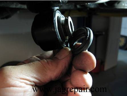
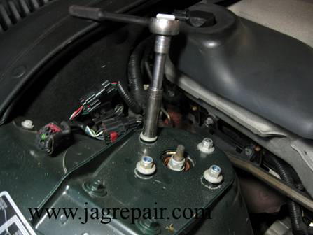
Removed the nut on the ball joint and it came right out. Shock
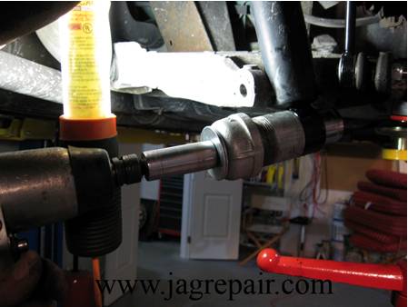
Bushing Replacement Lower I wanted to replace the bushings with the shock still mounted on the car and I did. It took a little doing but was successful on the rear shocks but the fronts I was better off removing them to do the job. My shock bushing device consisted of a 1 1/8 in socket to push the bushing out to a 1 ½ in pipe to receive the bushing and a 1 ¼ in socket to push the new bushing back into place. I used carriage bolts to push out the bushing and carriage bolts to push the new bushing in place. The carriage bolt was selected because it fit well into the socket head to prevent it from turning at that end. I used PB Blaster to spray all 4 shock mounts prior to my doing anything. I used an impact wrench to tighten the nut and a hammer to get it to move. The first bushing would not move so I tapped the head of the bolt at the socket and it was on its way out. You will also notice I used a standard not an impact socket. I did not have a deep well impact socket. A true test for my SK socket! After my testing the bushing puller I am having a few custom parts made along with a better bolt to use. A few on my bolts bent in the process. Rear
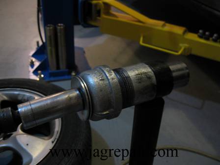
This is one of the rear shocks. I had to use my stand to push up on the hub to get room to do the job.
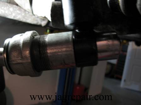
Just another angle pushing the bushing out
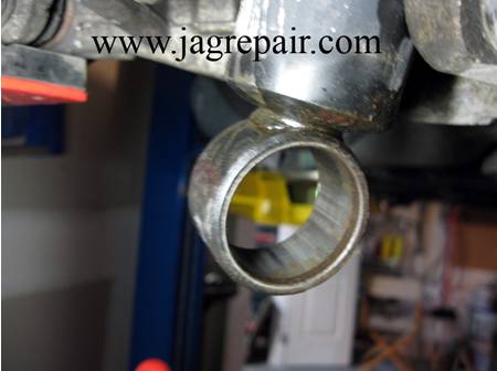
After the bushing removed
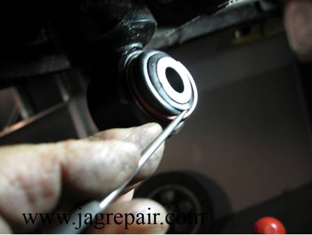
When I examined the old bushing when it was out I noticed that the 1 1/8 in socket pinched the seal and bent the lip that holds it so I elected to remove the seal from the new bushing and found that my 1 ¼ in socket did not touch the lip so I used it to push the new one in place.
After the bushing was installed I reinstalled the seal Front
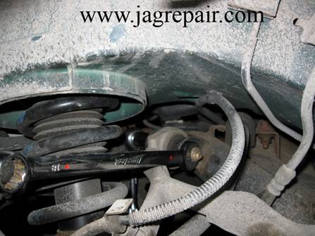
The front was a little more difficult. I had to remove the stabilizer link to get access to the shock bolt.
I removed the bolt and found that I was unable to access the bushing with the shock mounted on the car So I removed it.
4 bolts and it came out.
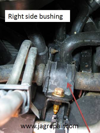
Replaced the last 2 bushings the same way as the rear and reinstalled the shock. I will post the new tool when I am sure it will work. At this point I drove the car and still had the rattle over a bump but not as bad so it went back on the lift. I elected to replace the Stabilizer Bar Bushings and by the way, it took care of the rest of the noise when going over a bump..
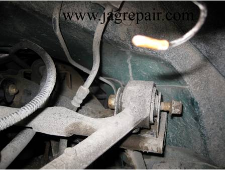
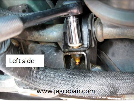
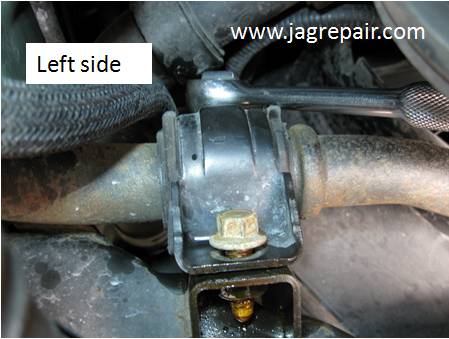
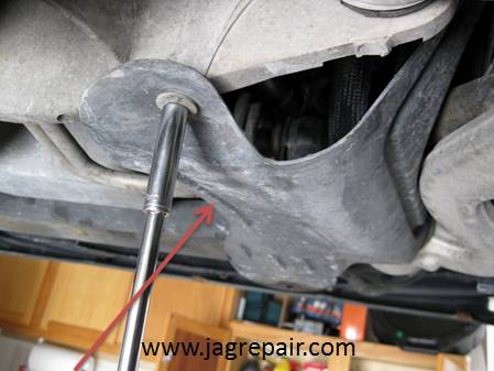
This is the left side facing out of the car. This bushing was not a problem to remove because I could use a socket. The photo above is the bolt on the engine side of the bushing. I should note I used a little PB Blaster on all the bolts first.
This is the access to the bumper side of the bushing.
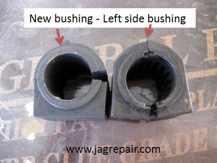
After the removal of the bushing I wanted to compare the old to the new. It seemed that the old one was a little different. I did find a TSB that addresses a problem with the bushing. It appears that Ford attempted to use the Thunderbird bushings but from the TSB my 2000 did not fall into the time frame they indicated but I am still a little suspicious.
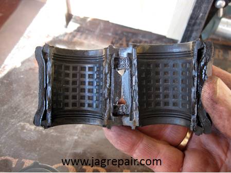
This is the inside of the removed bushing.
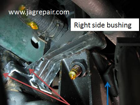
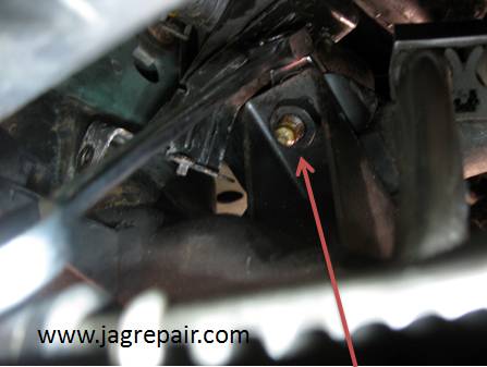
Off to the right side. Had to remove an additional cover, just one bolt.
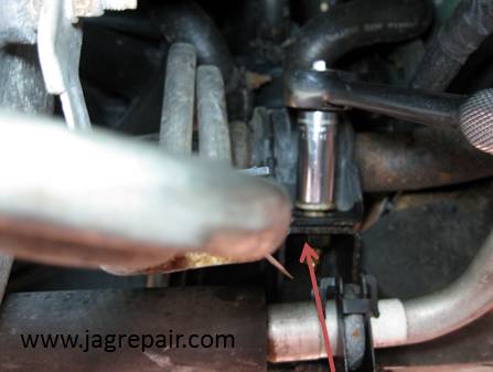
This side was a bit more difficult. I had to get the DCCV out of the way to get access to the one bolt on the bumper side. What I did was remove one bolt (the one to the far left) on the DCCV mounting bracket and pushed up on it to get access.
This is the other bolt on the engine side. Easy access.
Removed the engine side bolt.
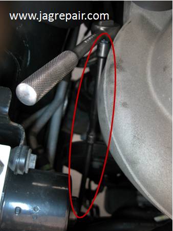
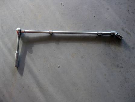
I had to use all my extensions to reach the bumper side bolt from the top. I also had to use a short socket with a universal to break it loose.
Once loose I used a ratchet box end wrench with a swivel head to work the bolt all the way out.
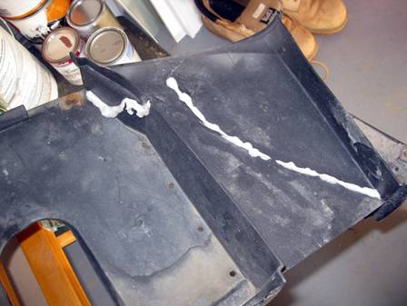
This is the Splash Pan that was damaged when I hit the road surface when exiting a parking lot. I used Gorilla Glue to make the repair. It seemed to work well. WOW, WHAT A RIDE! It was worth every bit of work I did!!
|
|
|